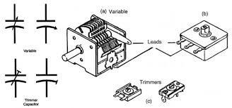
Variable capacitors, also known as tuning capacitors or trimmer capacitors, are electronic components that allow the capacitance value to be adjusted. They find applications in various electronic circuits where tuning or adjustment of capacitance is required. Here is an introduction to variable capacitors including their types, operation, applications, advantages, and disadvantages:
Types of Variable Capacitors:
-
Trimmer Capacitors: Small capacitors often used for fine-tuning applications and adjustments in circuits.
-
Tuning Capacitors: Larger capacitors used for tuning radio frequencies, antennas, and resonant circuits.
-
Variable Air Capacitors: Capacitors consisting of two sets of metallic plates separated by air dielectric, controlled by rotating one set of plates relative to the other to change capacitance.
-
Varactor Diodes (Varicap): Semiconductor devices exhibiting variable capacitance characteristics based on the reverse-biased junction voltage.
Operation of Variable Capacitors:
- The capacitance value of a variable capacitor can be adjusted by changing the effective area of the capacitor plates or altering the distance between them.
- Typically, rotating a shaft or adjusting a trimmer screw changes the overlap area of the plates, thus changing the capacitance.
Applications of Variable Capacitors:
- Radio Frequency (RF) Tuning: Used in radio receivers, transmitters, antennas, and frequency tuning circuits.
- Oscillator Circuits: Employed in LC oscillators for adjusting the frequency of oscillation.
- Filters: Variable capacitors are used in adjustable filters to control the cutoff frequency.
- Tuned Circuits: Key components in resonant circuits for selecting specific frequencies.
- Voltage-Controlled Oscillators (VCOs): In VCOs and frequency synthesizers for frequency modulation.
Advantages of Variable Capacitors:
- Allow precise adjustment of capacitance in electronic circuits.
- Facilitate frequency tuning to desired values in RF applications.
- Provide flexibility in circuit design and optimization for specific requirements.
Disadvantages of Variable Capacitors:
- Mechanical wear and tear over time, affecting performance.
- Limited lifespan compared to fixed capacitors.
- Size and cost may be higher for high capacitance ranges.
Variable capacitors play a crucial role in electronic circuit design, especially in applications requiring precise tuning and frequency control. By enabling adjustment of capacitance values, they offer flexibility and optimization in various electronic systems. Understanding the types, operation, applications, strengths, and limitations of variable capacitors is essential for their effective integration into electronic designs and circuits.
Capacitor Identification
When identifying a capacitor, you may come across markings or codes on the capacitor that provide information about its specifications. Here is a general guide to help you decode and identify information from the markings on a capacitor:
Capacitor Markings:
-
Capacitance Value: The capacitance value is usually indicated in picoFarads (pF), nanoFarads (nF), or microFarads (uF). For example, a marking of "104" represents 10 x 10^4 pF = 100,000 pF = 0.1 uF.
-
Tolerance: The tolerance of the capacitor indicates the variation in capacitance from the stated value. Common tolerances include ±5%, ±10%, ±20%, etc.
-
Voltage Rating: The maximum voltage the capacitor can handle without damage. It is typically indicated in volts (V).
-
Dielectric Material: Some capacitors may have markings indicating the dielectric material used, such as X7R, Y5V, NP0, etc.
-
Manufacturing Date/Code: Some capacitors may have a date code indicating the manufacturing date or lot code.
-
Manufacturer Code: The manufacturer of the capacitor may be identified by a logo, name, or code.
Examples:
-
104K: This code could represent a capacitor with a value of 100,000 pF (or 0.1 uF) with a tolerance specified separately.
-
473J: This code might signify a 47,000 pF (or 47 nF) capacitor with a tolerance specified elsewhere.
-
474K 16V: This marking indicates a 470,000 pF (or 0.47 uF) capacitor with a 10% tolerance rating and a maximum voltage rating of 16V.
How to Read:
- Start by identifying the numerical values on the capacitor, which represent the capacitance in picoFarads.
- Look for any letters following the numbers, which could indicate the tolerance or other specific characteristics.
- Check for any additional markings that may provide information about the voltage rating, date code, or manufacturer.
Remember that capacitor markings can vary depending on the manufacturer and capacitor type. If you are unsure about the specifications of a particular capacitor, referring to the manufacturer's datasheet or contacting the manufacturer directly can provide accurate information about the component.
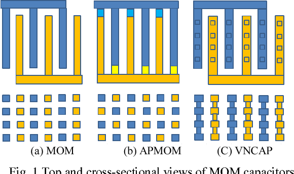
Classification of Variable Capacitors
Variable capacitors can be classified based on various criteria, such as construction, method of variation, applications, and technologies used. Here are some common classifications of variable capacitors:
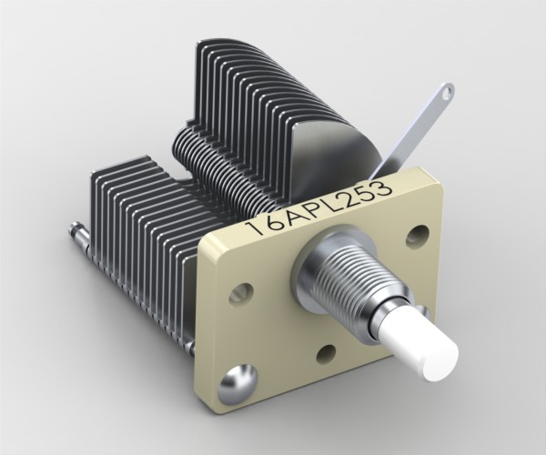
1. Construction Type:
- Air Variable Capacitors: These capacitors use air as the dielectric material and are commonly used in radio frequency (RF) tuning circuits and high-voltage applications.
- Trimmer Capacitors: Compact capacitors with a small range of capacitance adjustment, typically used for fine-tuning applications in circuits.
- Screw Adjustable Capacitors: Capacitors where the capacitance can be adjusted by turning a screw, altering the overlap area of the plates.
- Rotor-Stator Capacitors: Capacitors with two sets of plates (rotor and stator) that can be rotated relative to each other to change the capacitance.
2. Method of Variation:
- Mechanical Variable Capacitors: Capacitors where the capacitance changes mechanically by adjusting the physical components.
- Voltage Variable Capacitors (Varactors): Capacitors whose capacitance changes with the applied voltage, typically using a reverse-biased pn junction.
3. Applications:
- Tuning Capacitors: Used in radio frequency (RF) circuits, antennas, and resonant circuits for frequency tuning.
- Trimmer Capacitors: Fine adjustments in electronic circuits requiring minor capacitance changes.
- Voltage-Controlled Capacitors (Varactors): Used in oscillators, filters, and tuning circuits where capacitance is controlled by changing the voltage.
4. Technology Used:
- Variable Capacitors with Silicon Dielectric: Capacitors where silicon is used as the dielectric material.
- Variable Capacitors with Ceramic Dielectric: Capacitors using ceramic material as the dielectric, offering stability and reliability.
- Variable Capacitors with Air Dielectric: Capacitors using air as the dielectric, often used in high-frequency applications.
5. Frequency Range:
- Low to Medium Frequency Variable Capacitors: Capacitors suitable for applications in the lower to medium frequency ranges.
- High-Frequency Variable Capacitors: Capacitors designed to operate efficiently at high frequencies, commonly used in RF applications.
6. Temperature Stability:
- Temperature-Compensated Variable Capacitors: Capacitors designed to minimize variation in capacitance with changes in temperature.
- Non-Temperature-Compensated Variable Capacitors: Capacitors where the capacitance may vary significantly with temperature changes.
7. Mounting Type:
- Surface Mount Variable Capacitors: Capacitors designed for surface-mount soldering on PCBs.
- Through-Hole Variable Capacitors: Capacitors with leads for through-hole mounting on circuit boards.
These classifications help in understanding the different types of variable capacitors available, their characteristics, and their suitability for various applications. When selecting a variable capacitor, it is essential to consider criteria such as frequency range, capacitance range, stability, and environmental factors to ensure optimal performance in the intended application.
Structure and working principle of variable capacitors
Structure of Variable Capacitors:
Variable capacitors come in various designs, but they typically consist of two metal plates separated by a dielectric material. The separation between the plates or the area of overlap can be adjusted, leading to a change in the capacitance value. Here is a general structure of variable capacitors:
-
Metal Plates: The capacitor consists of two conductive plates, typically made of metal, that store opposite charges when a voltage is applied.
-
Dielectric Material: The dielectric material separates the plates and determines the capacitance value. Common dielectric materials include air, ceramic, plastic, or mica.
-
Adjustment Mechanism: Variable capacitors have a mechanism that allows for the adjustment of the distance between the plates or the area of overlap. This mechanism can involve rotating a shaft, turning a screw, or sliding plates.
Working Principle of Variable Capacitors:
The working principle of a variable capacitor is based on the fundamental equation of capacitance:
[ C = \frac{\varepsilon A}{d} ]
Where:
- ( C ) is the capacitance.
- ( \varepsilon ) is the permittivity of the dielectric material.
- ( A ) is the surface area of the plates.
- ( d ) is the separation distance between the plates.
When a voltage is applied to the variable capacitor, an electric field is created between the plates due to the build-up of electric charges. The capacitance value of the variable capacitor is directly proportional to the surface area of the plates and the permittivity of the dielectric material, and inversely proportional to the distance between the plates.
By adjusting the distance between the plates or changing the surface area of overlap, the effective capacitance can be varied. This adjustment changes the electrostatic field and the amount of charge that the capacitor can store, thereby altering the capacitance value.
In summary, the working principle of variable capacitors involves adjusting the physical characteristics of the capacitor, such as plate separation or area of overlap, to modify the capacitance. This adjustability allows variable capacitors to be used in applications where precise tuning of capacitance is required, such as in radio frequency circuits, filters, oscillators, and tuning circuits.
Trimmer capacitors
Trimmer capacitors are a type of variable capacitor designed for precise adjustment of capacitance in electronic circuits. They are often smaller in size and are used in applications where fine-tuning or trimming of capacitance values is necessary. Here is an overview of trimmer capacitors, including their structure, working principle, applications, advantages, and considerations:
Structure of Trimmer Capacitors:
-
Capacitor Plates: Trimmer capacitors consist of two conducting plates separated by a dielectric material. One of the plates is fixed, while the other can be adjusted for capacitance tuning.
-
Adjustment Mechanism: The movable plate, typically controlled by a screw or a knob, allows for the adjustment of capacitance by changing the overlap area with the fixed plate.
-
Dielectric Material: The dielectric material between the plates determines the capacitance value and may vary based on the capacitor's intended use.
Working Principle of Trimmer Capacitors:
- By adjusting the movable plate with respect to the fixed plate, the effective area of overlap changes, thereby altering the capacitance value.
- Capacitance in trimmer capacitors is directly proportional to the area of overlap between the plates and the permittivity of the dielectric material.
- Turning the screw or knob adjusts the distance or area between the plates, thereby fine-tuning the capacitance value in the circuit.
Applications of Trimmer Capacitors:
-
Radio Frequency (RF) Circuits: Used in RF tuning circuits, antennas, filters, and transmitters where precise capacitance adjustment is required for optimal performance.
-
Oscillator Circuits: Employed in oscillators, frequency synthesizers, and phase-locked loops for frequency tuning and stability.
-
Signal Processing Circuits: Used in signal filters, impedance matching networks, and active/passive networks to adjust signal characteristics.
Advantages of Trimmer Capacitors:
-
Precise Capacitance Adjustment: Trimmer capacitors offer precise tuning of capacitance values for circuit optimization.
-
Compact Size: Their small form factor makes them suitable for applications where space is limited.
-
Repeatable Adjustments: Trimmer capacitors allow for adjustments that can be accurately repeated during circuit calibration.
Considerations:
-
Temperature Stability: Trimmer capacitors may exhibit changes in capacitance with temperature variations, impacting circuit performance.
-
Voltage Ratings: Ensure that the trimmer capacitor's voltage rating meets the requirements of the circuit to prevent damage.
Trimmer capacitors are valuable components in electronic circuit design, particularly in applications requiring precise adjustment and tuning of capacitance values. Their ability to finely tune capacitance makes them essential in various RF and high-frequency circuits, where optimal performance is critical.
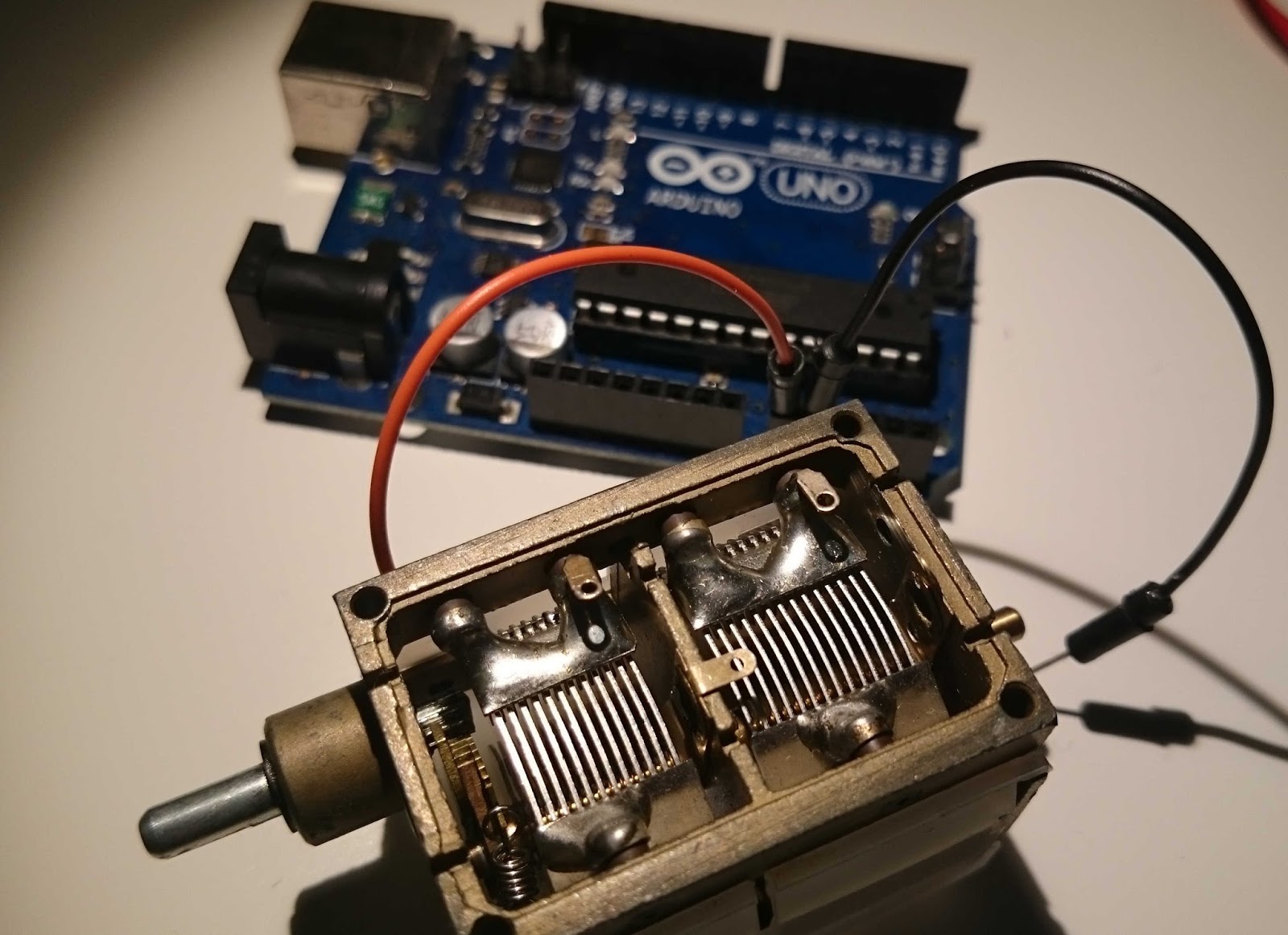
How to test a variable capacitor?
Testing a variable capacitor involves verifying its capacitance value and checking for any potential faults or defects that may affect its performance in a circuit. Here are steps to test a variable capacitor using a multimeter:
Tools Required:
- Digital Multimeter: Set to measure capacitance.
- Alligator Clips or Test Probes: To connect the variable capacitor to the multimeter.
Steps to Test a Variable Capacitor:
- Discharge the Capacitor:
- Before testing, ensure the variable capacitor is discharged to prevent any electrical shock.
- Determine the Capacitor Leads:
- Identify the terminals of the variable capacitor. Typically, one terminal is the common terminal, and the other connects to the moving plate.
- Set up the Multimeter:
- Turn on the digital multimeter and set it to measure capacitance in the appropriate range. Choose a range higher than the expected capacitance value of the variable capacitor.
- Connect the Capacitor to the Multimeter:
- Connect one lead of the multimeter to the common terminal of the variable capacitor and the other lead to the terminal connected to the moving plate.
- Read the Capacitance Value:
- The multimeter will display the capacitance value of the variable capacitor. Compare this value to the expected or rated capacitance of the capacitor.
- Rotate the Adjustment Mechanism:
- While monitoring the capacitance value on the multimeter, adjust the variable capacitor's mechanism (such as turning a screw or knob) to see if the capacitance changes smoothly.
- Check for Shorts or Open Circuits:
- Verify that there is no short circuit (zero capacitance reading) or open circuit (infinite capacitance reading) when testing the variable capacitor.
- Inspect for Physical Damage:
- Visually inspect the variable capacitor for any signs of physical damage, such as cracks, leaks, or burnt marks, which may indicate faults.
Interpreting Results:
-
Correct Capacitance Value: If the measured capacitance is close to the rated value and changes smoothly with adjustments, the variable capacitor is likely in good condition.
-
Incorrect Capacitance Reading: A significant deviation from the rated capacitance or erratic behavior during adjustments may indicate a faulty capacitor that requires replacement.
-
Shorts or Opens: A reading of zero capacitance (short) or infinite capacitance (open) suggests a faulty capacitor that needs to be replaced.
Regularly testing variable capacitors ensures their reliability and proper functioning in electronic circuits. Proper testing techniques help identify defective components and prevent circuit malfunctions due to capacitor issues.