1. Under what circumstances should a current fuse be used in a motor protection circuit?
In circuit protection applications, when a single fault occurs or a short circuit occurs in a parallel device, it is a very necessary choice to disconnect the fuse in time to protect personal safety and protect high-priced and important components.
2. Technical parameter requirements for fuses for motor protection circuits
① The rated voltage requirement of FUSE is greater than the line voltage
The fuse will work in three working states according to the current I of the line: normal working area, working blind area and fuse protection area. When the I value is less than 1 times the rated current value In of the fuse, the fuse is required not to break. We It is called the normal working area; when 1x In<I<2x ln, it is regarded as a blind area, and the fusing time of the fuse is difficult to define; when I is greater than 2ln, the fuse works in the fusing protection area. According to the designed melting point, it can be defined Fusing characteristics that meet UL safety regulations. The blown state of the fuse is roughly as follows:

Although the fuse is a current-sensitive component, the picture on the left reveals the process of the fuse blowing after overcurrent and heating. In fact, the safety at the moment of blowing has a great relationship with the rated voltage, such as flying foxes, combustion, and chemical energy leakage. All are unsafe fuses. Therefore, the rated voltage is one of the safety indicators considered.
②Interrupting capacity (Interrupting Rating) meets the requirement to safely cut off the circuit


Schematic diagram of specifications and parameters
According to theoretical calculations, the current Ir when a motor line is short-circuited = line voltage U/R line equivalent impedance. The breaking current of the fuse must be greater than the short-circuit current Ir to avoid unsafe fuse situations such as flying foxes, burning, and explosions. Therefore, you need to refer to the Interrupting Ratings indicator in the product specification when choosing.
③ Meet the surge current at the moment when the motor starts/can withstand the current peak value when the motor is stalled
In product applications, the moment the motor starts, a large surge current will be generated. If the motor is blocked, the current will rise rapidly. The impact current on the fuse will be based on the duration of the surge t1 and the internal resistance R of the line. Determined by the line voltage U, the fuse is required to withstand an overload current of 200% to 400% of the rated current for a slightly longer time. Therefore, higher requirements are placed on the fusing characteristics. Therefore, it is necessary to observe whether the fusing curve in the specification meets the application requirements.

Startup surge diagram

Fusing characteristic curve
3. AEM’s recommended solutions for motor protection
In response to the above requirements for motor protection, AEM Technology has developed a higher specification current fuse product series, namely the 1206 size HC series (10~40A @35VDC) and CM2822 series (20~125A@75VDC), which meet the needs of high-power Current motor operating requirements.

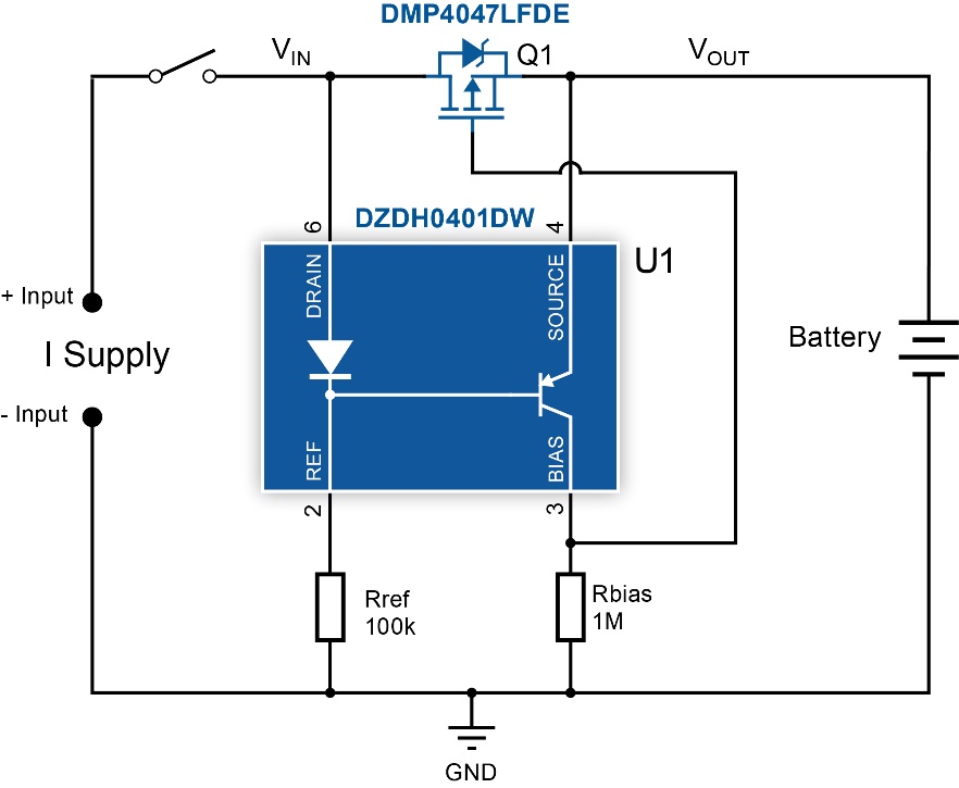
Example of fuse application circuit diagram
As shown in the figure, F1 fuse prevents accidental short-circuit events in circuit components such as MOSFETs connected in parallel at the back end, and promptly disconnects the protection. F2 acts to protect the power supply branch circuit. According to the calculation of the circuit power, the general input FUSE F1>F2, AEM's SMD fuse product array, provides the 1206 HC series for the Input F1 of the motor circuit, or the CM2822 series that meets higher power to choose from; F2 can provide applications A wider range of products (0.15A~8A) with different sizes and specifications are available to meet the requirements.
(1) Features of 1206HC series
Current specification: 10~40A, 35VDC, 350% overload melting point design, meeting most selection and application requirements


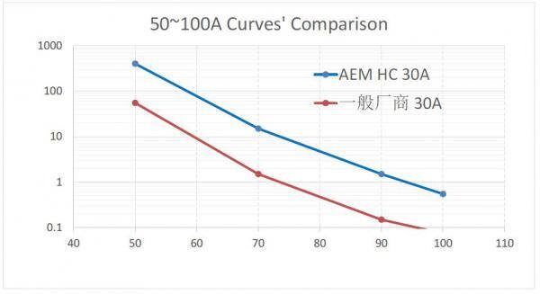
Taking the current specification 30A fuse as an example, by evaluating the time VS. current curve (melting characteristic curve) of the fuse, it can be found that AEM's HC30A has higher surge resistance at 200%~400%. As shown below.
(2) CM2822 series moving towards higher current specifications
AEM has developed fuse products with larger current specifications in response to the high breaking capacity requirements of different motor markets. The current specifications cover application scenarios of 20A~125A and 125VDC~75VDC.


In applications, one high-current fuse can be used to replace multiple fuses connected in parallel.

In practical applications, it is generally recommended that customers make reference selection based on the maximum peak operating current of the circuit's steady-state current, calculate the I²t of the surge current by capturing the actual surge current waveform, and compare it with the If²t of the fuse for accurate selection. Ensure that the fuse can meet the three application principles of "timely fuse protection when it should fuse, do not break when it should not fuse, and ensure safety at all times".