As wireless appliances become more popular in homes and industries, the need for battery discharge protection also arises. Two prominent examples are autonomous lawn mowers and robot vacuum cleaners that automatically return to their charging base when they need charging or are idle.
The way a self-propelled appliance is connected to a charger is usually to align a pair of metal contacts on the appliance with the corresponding contacts on the charger. Since these contacts are usually located on the bottom of the appliance, there is a risk of a short circuit when the appliance passes over an exposed metal object. The sweeping robot may pass through the metal closing strips of the carpet, or the lawn mower may encounter various metal objects hidden in the grass.
Therefore, the operational safety of unattended automated appliances needs to be considered, especially when a short circuit occurs at the charging port, which may release very high battery discharge current.
Battery discharge protection
There are many different ways to protect charging contacts and thus avoid short circuits. Install a removable shield or cover that protects the appliance when it is disconnected from the charger, or the contacts can be designed to retract. But this mechanical design adds extra cost, and the protective cover can crack or malfunction. In addition, a mechanically operated switch can also be added to the circuit design to automatically isolate the contacts after the electrical appliance is disconnected from the charger.
But using electronic protection circuits eliminates the need for moving parts and provides a more robust and reliable solution. One way this can be done is through a simple diode configuration. However, when the diode is forward biased, the voltage drop across it reduces the charging voltage delivered to the battery, causing unwanted power loss.
A diode rectifier with a typical forward voltage of VF = 0.55V results in a dissipation of 1.65W at 3A charging current (P = I x VF).
Some appliance manufacturers solve this problem by using MOSFETs for reverse discharge protection. When charging is turned on, the MOSFET's low on-resistance (RDS(on)) ensures minimal drop in charging voltage, ensuring optimal charging efficiency and battery life. In addition, power consumption is reduced to a minimum.
A P-type MOSFET with an RDS(on) of 33mΩ, such as the DMP4047LFDE, reduces the battery charging voltage to only 99mV, significantly reducing power dissipation to 0.297W (P = I2 x R).
ideal diode controller
Diodes Corporation's DZDH0401DW simplifies the circuit design required to control MOSFETs. The device is an ideal diode controller in a small SOT363 package measuring only 2.15mm x 2.1mm x 1mm. The small size helps engineers design devices with limited internal space, such as cordless appliances and small power tools. The device can also be used for redundant and hot-swappable power supplies, as well as general-purpose high-side gate drivers, providing high-side isolation switching solutions.
The DZDH0401DW is suitable for systems with operating voltages up to 40V and emulates an ideal diode by driving a P-channel MOSFET. The device operates as a differential amplifier and PMOS controller, minimizing forward current losses when the voltage sensed at the input is greater than the voltage at the output. Conversely, when the sensed input voltage is less than the output voltage, a high degree of isolation can be provided.
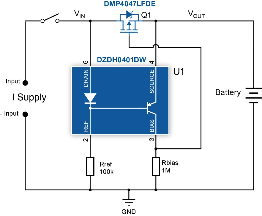
Battery discharge protection circuit for electrical appliances
Shows battery discharge protection application circuit on wireless appliances. When power is connected, the body diode of the MOSFET (Q1) becomes forward biased. The DZDH0401DW internal drain diode (Drain Diode) holds the base of the integrated PNP bipolar transistor at VIN – VF(DIODE), causing the transistor to not have enough VBE to turn on. As Q1's Gate Capacitance charges through the externally connected resistor Rbias, Q1 turns on and its RDS decreases, causing VDS to decrease simultaneously. The VBE across the transistor thus starts to rise and turns the transistor on. When Q1 RDS reaches its lowest value (RDS(on)), the VBE of the integrated transistor is at its highest value and IC is at its maximum value. Under these conditions, VGS should be high enough to ensure linear operation.
Rref and Rbias set the current through the drain diode and the collector of the integrated transistor respectively, so that VF(DIODE) is greater than VBE(on). Rbias determines the MOSFET's conduction speed. When the ideal diode circuit conducts, the internal transistor is turned off by the drain diode, causing the MOSFET voltage to drop. Rbias pulls the gate low and turns on the MOSFET. Choose the resistor value to minimize the circuit's quiescent current operation.
When power is disconnected, the input voltage is removed and VDS becomes less than the controller's shutdown threshold voltage (VT). Since Q1 is still on, the VIN node is the same as the battery's VOUT. This causes the voltage drop VREF across Rref to decrease. When the internal transistor turns on, the Q1 gate capacitance discharges through it and the MOSFET turns off, creating a high degree of isolation between the input and output. The value of Rref determines how quickly the MOSFET turns off. Lower resistance increases the base drive of the transistor, so the transistor shorts the gate faster, turning off the MOSFET.
in conclusion
MOSFETs with low on-resistance (RDS(on)) characteristics can be effectively used in battery discharge protection of consumer appliances when controlled as ideal diodes. This has always been the first choice for reverse current protection and power OR-ing circuits. device. A simple single-chip controller simplifies operation, saves space, improves battery performance and increases energy efficiency.