Thermistors:
Thermistors are temperature-sensitive resistors used in various circuits to measure temperature changes or to provide temperature compensation. They are available in two main types: NTC (Negative Temperature Coefficient) and PTC (Positive Temperature Coefficient) thermistors.
-
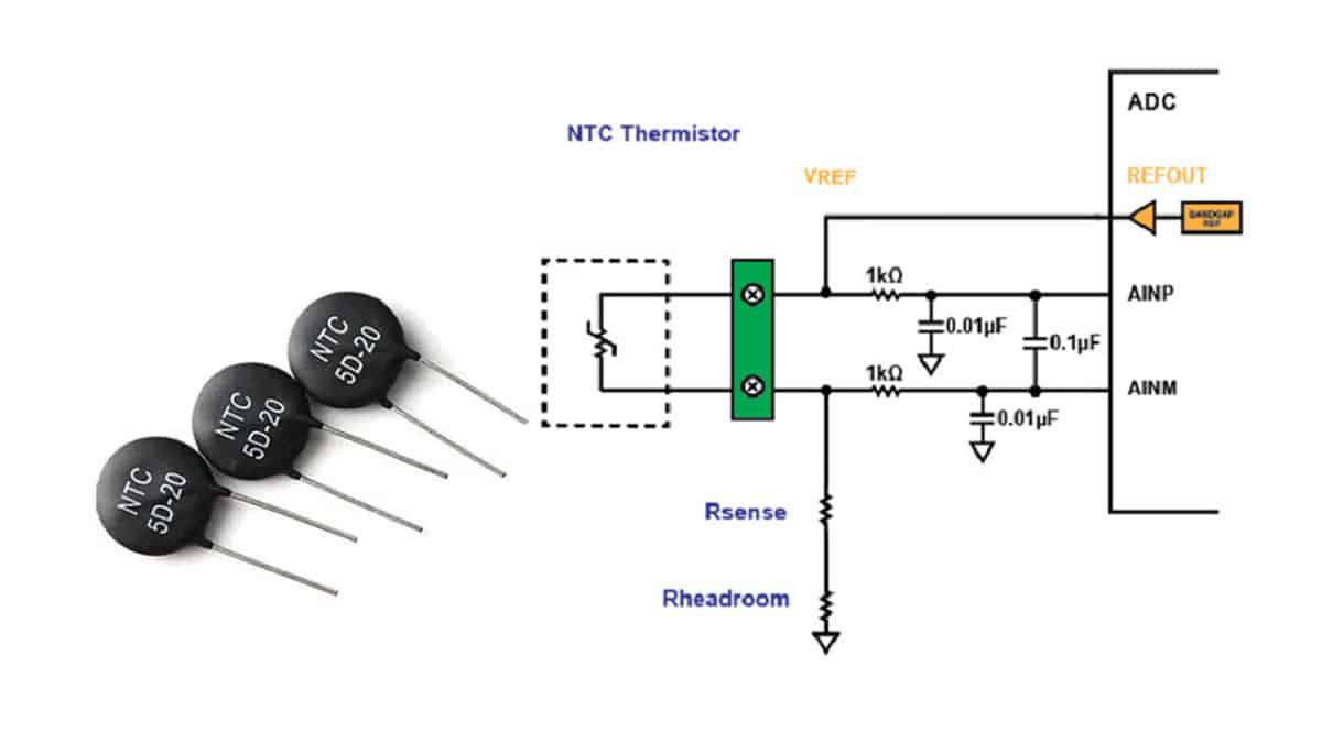
NTC Thermistors: Their resistance decreases as temperature increases. NTC thermistors are commonly used for temperature sensing, compensation, and control in circuits.
-
PTC Thermistors: Their resistance increases with temperature. PTC thermistors are often used in overcurrent protection, self-regulating heaters, and motor starting applications.
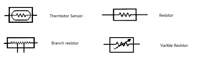
Thermistor Symbols:
Thermistors are represented in circuit diagrams using unique symbols to indicate their function.
-
NTC Thermistor Symbol:
.jpg)
- The NTC thermistor symbol consists of a resistor-like symbol with an arrow to represent the negative temperature coefficient behavior.
- The arrow typically points towards the resistor to depict the decreasing resistance with increasing temperature.
-
PTC Thermistor Symbol:
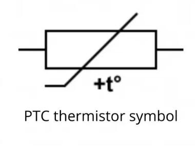
- The symbol for PTC thermistors includes a resistor-like symbol with the arrow pointing away, signifying the positive temperature coefficient behavior.
- The arrow points away from the resistor to indicate the resistance increases with temperature.
Common Applications of Thermistors:
- Temperature Sensing: Used in thermostats, temperature sensors, and temperature control circuits.
- Temperature Compensation: Ensure stable performance of components that are sensitive to temperature variations.
- Overcurrent Protection: PTC thermistors are employed in circuits to protect against excess current.
- Inrush Current Limiting: PTC thermistors can limit inrush currents in power supplies and electronic devices.
- Motor Starting: PTC thermistors are used for motor starting applications to prevent damage due to locked rotor conditions.
Conclusion:
Thermistors are valuable components in electronics for temperature measurement, compensation, and control. By understanding the characteristics of NTC and PTC thermistors and recognizing their symbols in circuit diagrams, engineers and hobbyists can effectively incorporate these components into their designs for temperature-sensitive applications.
The Applications Of Thermistor Symbols
The symbols used to represent thermistors in electrical or electronic circuit diagrams play a crucial role in conveying information about the type and function of the thermistor within the circuit. Here are some key applications of thermistor symbols in various contexts:
1. Circuit Design and Analysis:
- Identification: The use of thermistor symbols helps engineers and technicians quickly identify thermistors within circuit diagrams, simplifying analysis and troubleshooting.
- Interpretation: By recognizing the thermistor symbols, individuals can understand how temperature-sensitive components are integrated into a circuit and their intended function.
2. Documentation and Communication:
- Schematic Drawings: Thermistor symbols are essential components of schematic drawings, providing a standardized representation that facilitates communication among designers, technicians, and manufacturers.
- Technical Manuals: In technical manuals and documentation, thermistor symbols help in explaining circuit configurations, enabling clearer instructions for assembly and maintenance.
3. Education and Training:
- Learning Aid: Thermistor symbols serve as educational tools for students studying electronics, guiding them in understanding the role of thermistors in circuits and how they are denoted in diagrams.
- Training Purposes: In training programs for electronics professionals, thermistor symbols are used to teach individuals how to interpret and work with various components effectively.
4. Standardization and Consistency:
- Industry Standards: Thermistor symbols adhere to industry-standard conventions, ensuring consistency in circuit diagrams across different organizations, projects, and manufacturers.
- Efficiency: Standard symbols streamline the design and manufacturing processes by promoting a common understanding of thermistor representation in electrical schematics.
5. Electronics Integration:
- Integration with CAD Tools: Computer-aided design (CAD) software and tools incorporate thermistor symbols for designing circuits digitally, allowing for accurate representation and simulation of electronic systems.
- Simulation: When simulating circuits, the inclusion of thermistor symbols enables engineers to model temperature-dependent behavior and analyze the impact of thermistors on overall circuit performance.
6. Troubleshooting and Maintenance:
- Fault Diagnosis: Thermistor symbols aid in diagnosing circuit faults and failures, helping technicians pinpoint issues related to temperature sensing or compensation components.
- Repair Guidance: When repairing electronic equipment, thermistor symbols assist technicians in identifying and replacing faulty thermistors accurately.
In summary, the applications of thermistor symbols extend beyond mere graphical representation in circuit diagrams. They serve as essential tools for communication, education, standardization, efficiency in design and manufacturing processes, and troubleshooting in the field of electronics and electrical engineering. Understanding and utilizing thermistor symbols effectively contribute to the seamless integration of thermistors in various electronic systems and circuits.

The Advantages And Limitations Of Thermistor Symbols
-
Clarity and Communication:
- Clear Representation: Thermistor symbols provide a standardized and clear visual representation of thermistors in circuit diagrams, facilitating effective communication among engineers, technicians, and designers.
-
Efficient Design and Analysis:
- Design Efficiency: By using thermistor symbols, designers can quickly identify temperature-sensitive components in circuits, leading to more efficient design processes.
- Analysis Aid: Symbols help in analyzing circuit configurations, enabling engineers to assess the impact of thermistors on circuit performance.
-
Standardization:
- Consistency: Standard symbols promote uniformity in circuit diagrams across different projects, industries, and organizations, ensuring a common understanding of thermistor representation.
-
Educational Value:
- Learning Tool: Thermistor symbols serve as educational aids in teaching electronics concepts, helping students understand the role and placement of thermistors in circuits.
-
Troubleshooting Support:
- Diagnostic Assistance: Symbols aid in diagnosing circuit issues related to temperature sensing or compensation components, guiding technicians in identifying and resolving faults efficiently.
Limitations of Thermistor Symbols:
-
Complexity and Specialization:
- Limited Detail: Symbols may not convey detailed information about specific thermistor characteristics or configurations, requiring additional documentation for a comprehensive understanding.
-
Interpretation Challenges:
- Knowledge Dependency: Effective interpretation of symbols depends on the viewer's knowledge of standard representations, potentially posing challenges for individuals unfamiliar with symbol conventions.
-
Contextual Understanding:
- Lack of Context: Symbols alone may not provide context-specific information about thermistor applications or operational conditions, necessitating supplementary descriptions or annotations.
-
Varied Representation:
- Symbol Variability: Different schematic diagrams or software tools may use slightly varied thermistor symbols, leading to potential confusion or interpretation discrepancies in certain contexts.
-
Limited Functionality Information:
- Function Detail: Symbols may not convey the specific function or purpose of thermistors in a circuit beyond their basic identification as temperature-sensitive resistors.
Balancing Advantages and Limitations:
- Supplementary Documentation: Providing additional information or annotations alongside thermistor symbols can enhance their usefulness and address limitations related to complexity or interpretation challenges.
- Training and Education: Ensuring that individuals working with circuit diagrams are familiar with standard symbol conventions can mitigate potential confusion and improve clarity in communication.
- Integrated Design Tools: CAD software and electronic design tools that incorporate standardized thermistor symbols can streamline design processes and aid in efficient circuit analysis.
- Combined Representation: Combining thermistor symbols with text labels or callouts can offer a more comprehensive understanding of thermistor configurations and functions within circuits.
In conclusion, while thermistor symbols offer significant advantages in simplifying circuit representation and communication, acknowledging their limitations and employing strategies to address potential challenges can enhance their effectiveness in conveying essential information about thermistors in electronic circuits.