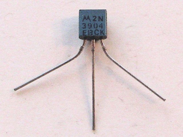
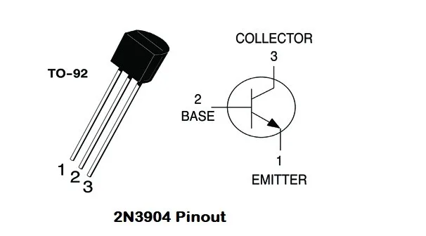
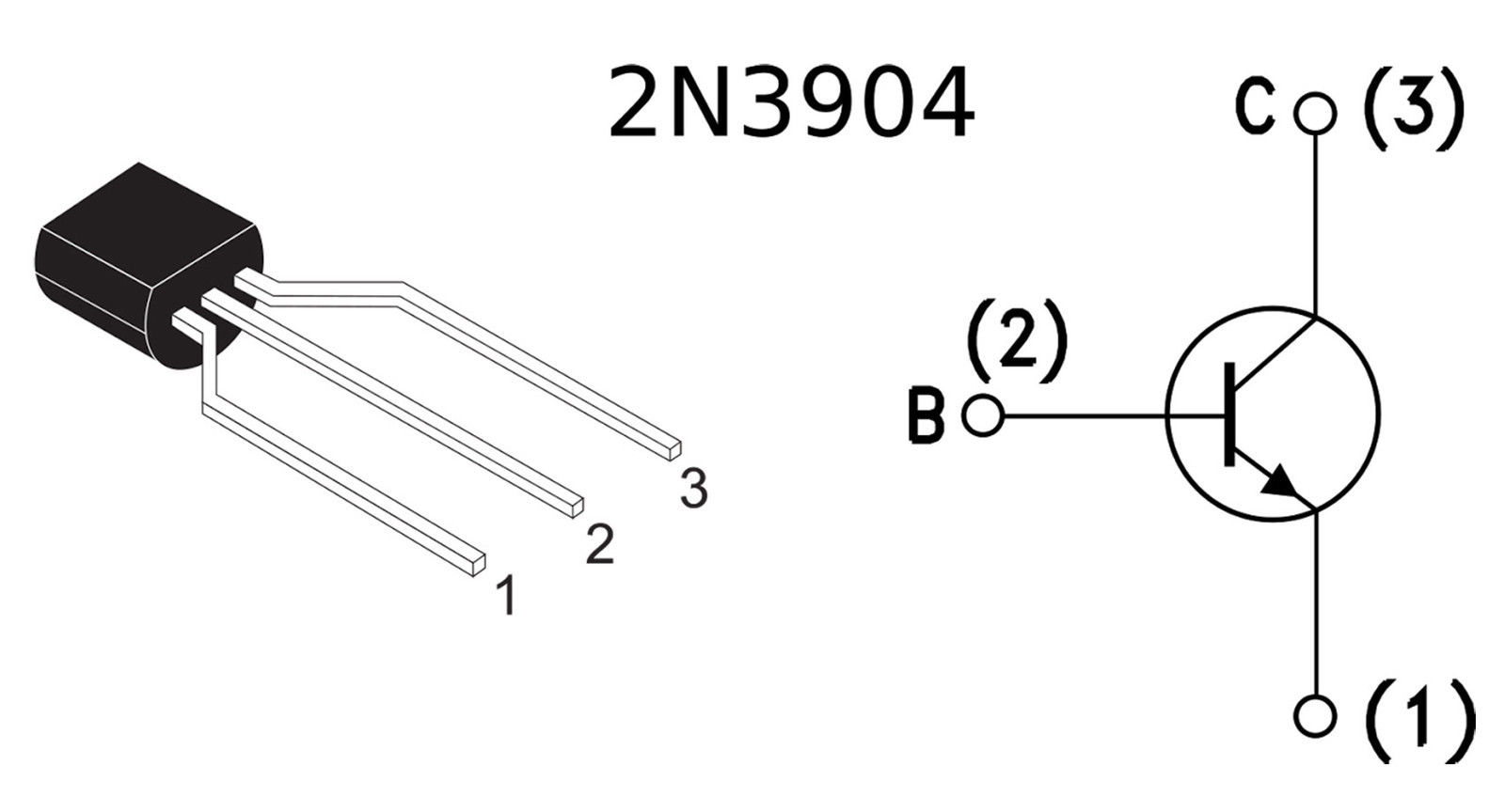
The 2N3904 is a popular NPN bipolar junction transistor (BJT) commonly used for signal amplification and switching purposes. Here's an overview of its application circuit, usage, and operating point selection:
Application Circuit: The 2N3904 can be used in various application circuits, including amplification and switching. For simple signal amplification, a common-emitter configuration is often employed. Here's a basic application circuit using the 2N3904 as a voltage amplifier:
In this circuit:
- Vcc is the positive power supply voltage.
- R1 provides biasing for the base-emitter junction.
- R2 provides the collector load resistor.
- Vout is the amplified signal output.
Usage: The 2N3904 offers a wide range of applications, including:
-
Amplification: It is commonly used for small-signal amplification in audio amplifiers, preamplifiers, and other low-power signal processing circuits.
-
Switching: The transistor can operate as a switch, controlling the flow of current in digital logic circuits, interface circuits, and other switching applications.
-
Oscillator Circuits: The 2N3904 can be utilized in oscillator circuits, such as relaxation oscillators or RC oscillators, to generate periodic waveforms.
Operating Point Selection: The operating point of the 2N3904 transistor refers to the chosen DC bias conditions that determine the transistor's behavior and provide suitable amplification or switching characteristics. The operating point is commonly determined by selecting appropriate biasing resistors.
Here are some general guidelines for selecting the operating point:
-
Biasing Resistors: Choose base and collector resistors (R1 and R2 in the application circuit) to set the desired DC biasing voltage levels and current flow. This determines the appropriate quiescent point for the transistor.
-
DC Collector Current (Ic): Determine the desired DC collector current according to the application requirements and the transistor's datasheet specifications.
-
Base Current (Ib): Calculate the base current required for the desired collector current using the transistor's current gain (hFE) and the desired collector current.
-
Voltage Dividers: If necessary, employ voltage dividers or biasing techniques to set the appropriate base voltage for biasing the 2N3904.
-
Thermal Considerations: Consider the power dissipation and thermal characteristics of the 2N3904 to ensure it operates within its safe operating limits. Adequate heat sinking may be required in high-power applications.
It's important to consult the 2N3904 datasheet and consider the specific parameters, limitations, and recommendations provided by the manufacturer to ensure proper operating conditions and reliable performance.
Note: The exact values of resistors and biasing conditions depend on the specific circuit requirements and the desired operating characteristics. Advanced analysis and design considerations may be required for complex applications or high-frequency operation.
.jpg)